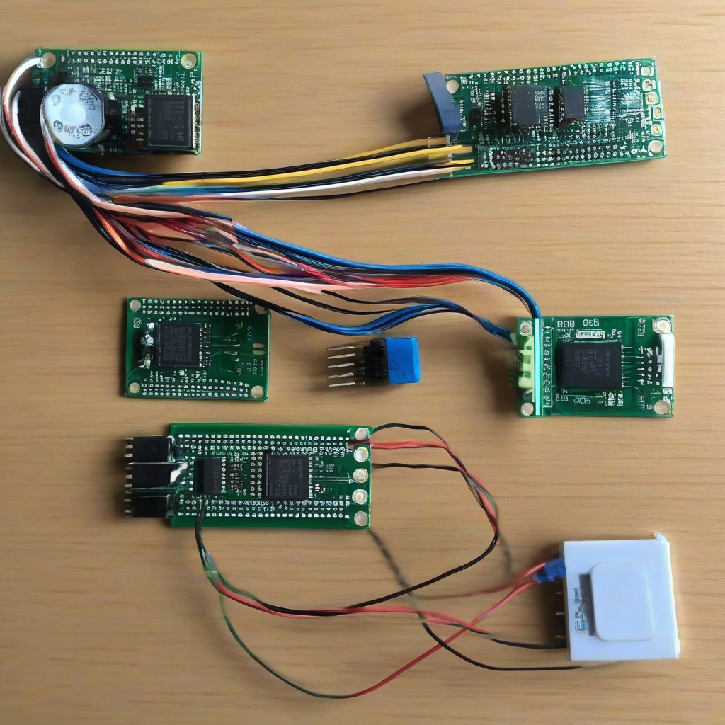
stm32f103c8t6 sensor module connections
图片类型
Default
提示词
1. Wiring STM32F103C8T6 with MAX30102 Heart Rate Sensor Module PB6 (I2C Clock) connected to the SCL pin of MAX30102 PB7 (I2C Data) connected to the SDA pin of MAX30102 3.3V power connected to the VCC pin of MAX30102 GND connected to the GND pin of MAX30102 2. Wiring STM32F103C8T6 with MAX30100 Blood Oxygen Sensor Module PB8 (I2C Clock) connected to the SCL pin of MAX30100 PB9 (I2C Data) connected to the SDA pin of MAX30100 3.3V power connected to the VCC pin of MAX30100 GND connected to the GND pin of MAX30100 3. Wiring STM32F103C8T6 with MPU6050 Six-Axis Sensor Module PB10 (I2C Clock) connected to the SCL pin of MPU6050 PB11 (I2C Data) connected to the SDA pin of MPU6050 3.3V power connected to the VCC pin of MPU6050 GND connected to the GND pin of MPU6050 4. Wiring STM32F103C8T6 with HC-05 Bluetooth Module PA9 (TX) connected to the RXD pin of HC-05 PA10 (RX) connected to the TXD pin of HC-05 3.3V power (or 5V with level conversion) connected to the VCC pin of HC-05 GND connected to the GND pin of HC-05 5. Wiring STM32F103C8T6 with OLED Display (0.96 inch SPI Interface) PA5 (SPI Clock) connected to the SCL pin of OLED PA7 (SPI Data) connected to the SDA pin of OLED PA4 (Data/Command Select) connected to the DC pin of OLED PA3 (Reset) connected to the RES pin of OLED 3.3V power connected to the VCC pin of OLED GND connected to the GND pin of OLED 6. Wiring STM32F103C8T6 with TP4056 Charging Management Module and Lithium Battery External power (5V USB) connected to the VCC pin of TP4056 GND connected to the GND pin of TP4056 Lithium battery positive terminal connected to the BAT pin of TP4056 Lithium battery negative terminal connected to the GND pin of TP4056 **STM32F103C8T6's ADC pin (e.g., PA0)** connected to the node of the battery voltage divider circuit (via R1 and R2) 7. Wiring STM32F103C8T6 with Buzzer and Vibration Motor PB0 connected to the positive terminal of the buzzer (active or driven by a transistor for passive) Buzzer negative terminal connected to the GND pin of STM32F103C8T6 PB1 connected to one end of the vibration motor The other end of the vibration motor connected to the GND pin of STM32F103C8T6
提示词
1. STM32F103C8T6与MAX30102心率传感器模块连线 PB6(I2C时钟)连接到MAX30102的SCL引脚 PB7(I2C数据)连接到MAX30102的SDA引脚 3.3V电源连接到MAX30102的VCC引脚 GND连接到MAX30102的GND引脚 2. STM32F103C8T6与MAX30100血氧传感器模块连线 PB8(I2C时钟)连接到MAX30100的SCL引脚 PB9(I2C数据)连接到MAX30100的SDA引脚 3.3V电源连接到MAX30100的VCC引脚 GND连接到MAX30100的GND引脚 3. STM32F103C8T6与MPU6050六轴传感器模块连线 PB10(I2C时钟)连接到MPU6050的SCL引脚 PB11(I2C数据)连接到MPU6050的SDA引脚 3.3V电源连接到MPU6050的VCC引脚 GND连接到MPU6050的GND引脚 4. STM32F103C8T6与HC-05蓝牙模块连线 PA9(TX)连接到HC-05的RXD引脚 PA10(RX)连接到HC-05的TXD引脚 3.3V电源(或5V,需电平转换)连接到HC-05的VCC引脚 GND连接到HC-05的GND引脚 5. STM32F103C8T6与OLED显示屏(0.96寸SPI接口)连线 PA5(SPI时钟)连接到OLED的SCL引脚 PA7(SPI数据)连接到OLED的SDA引脚 PA4(数据/命令选择)连接到OLED的DC引脚 PA3(复位)连接到OLED的RES引脚 3.3V电源连接到OLED的VCC引脚 GND连接到OLED的GND引脚 6. STM32F103C8T6与TP4056充电管理模块及锂电池连线 外部电源(5V USB)连接到TP4056的VCC引脚 GND连接到TP4056的GND引脚 锂电池正极连接到TP4056的BAT引脚 锂电池负极连接到TP4056的GND引脚 **STM32F103C8T6的ADC引脚(如PA0)**连接到电池电压分压电路的节点(通过R1和R2) 7. STM32F103C8T6与蜂鸣器及震动马达连线 PB0连接到蜂鸣器正极(有源或通过三极管驱动无源) 蜂鸣器负极连接到STM32F103C8T6的GND引脚 PB1连接到震动马达一端 震动马达另一端连接到STM32F103C8T6的GND引脚